
Data Transformation
Standard Manual for Digital Transformation (IoT) Module
- Introduction
- Vignette Contents
- The Software
- The Hardware
- The CPU
- Microcontrollers
- Sensors and devices
- The tablet
- Assembly
- Arduino Wiring
- ESP32 Wiring
- Vignette Setup and use instructions
- Sensors and devices
- The Tablet
- Starting up
- Shutting Down
- Troubleshooting
Introduction
IoT systems are a critical first step into applying AI and Industry 4.0 technologies, and this module aims to showcase some fundamental capabilities of this type of applications, as well as emphasizing the existence of very accessible options to start diving into them. Through this module we seek to debunk the wrong notion that a high degree of programming knowledge is required to work on IoT applications, as well as showcasing that it is possible to create IoT solutions with minimal budget.
Vignette contents
The complete bill of materials for the Vignette, not counting the base table/structure, is the following:
- ZimaBoard 432
- Control Buttons Set (Button Box)
- Temperature and Humidity sensor (1 sensor)
- LED Tower
- Red Ethernet cables
- Sonoff smart plugs
- Displayport to HDMI adapter (for ZimaBoard)
- Surge protector block
- Wireless Keyboard & Mouse set
- Arduino Opta AFX00002
- ESP32 (model ESP-WROOM-32, Type-C USB, 38 pins)
- Circuit Box enclosing
- Ubiquiti Networks Router
- Ubiquiti Power-over-Ethernet(PoE) Injector
- PoE Splitter USB-C, 5V
- 3 1Kg Load cells
- CTA Digital Tablet Mount & Enclosure
- Amazon Fire 10 HD tablet
1. The Software
The Vignette is composed of 2 main platforms: Home Assistant and Node-Red.
Home Assistant is an IoT hub platform which the Vignette revolves around. While its intended use cases are smart home applications, its functionality serves the same purpose as an industrial IoT application. As opposed to a more advanced industrial IoT platform, Home Assistant works better on a smaller scale. It is also open-source software and, along with extensive documentation and support from other users sharing their work, it is very intuitive and user friendly.
Node-Red is a visual programming platform that simplifies connectivity between devices and general flows of data, as well as acting upon these. It provides a code-less platform for programming functionality and interactions between devices without the need to learn a programming language.
While Node-Red alone also has its own IoT and dashboarding capabilities, Home Assistant is considerably more flexible and provides better support for device connectivity, as well as having a more straight-forward dashboard management, and as such we use it for those tasks, while using Node-Red for easier programming and automations.
2. The Hardware
Apart from the main table, the router that provides internet connectivity and all the necessary cables, there are 3 types of components in this Vignette: The main computer, the microcontrollers and the sensors.
2.1 The CPU
For the main computer we use a Zimaboard 432, which hosts both Home Assistant and Node-Red platforms, as well as some other minor software that helps tie everything together. It turns on automatically when powered up and is set up to immediately start up Home Assistant and Node-Red. (See Vignette Instructions section for more details on starting up the Vignette)
2.2 Microcontrollers
In order collect sensor data we use microcontrollers, which are programmed to translate sensor electrical signals into actual numerical data.
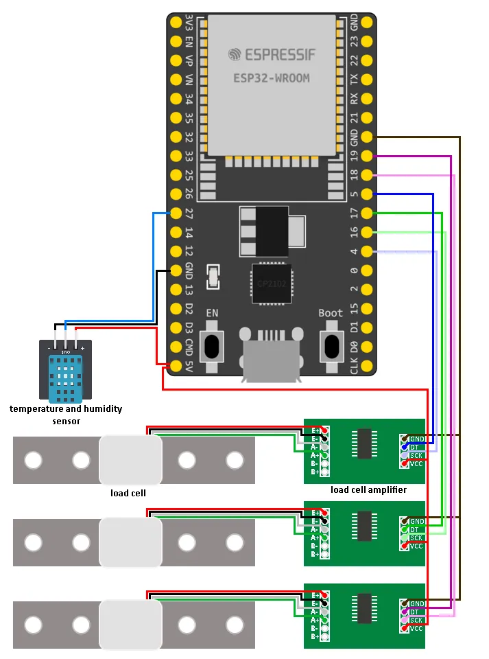
We have two sensors: an ESP32 and an Arduino OPTA. The ESP32 is a standard digital 3V and 5V I/O programmable microcontroller, which based on its program translates sensor signals into actual values. Its being held on the circuit box by a special mount that acts as a convenient add-on for handling wiring. The ESP32 connects to Home Assistant through a wireless Wi-Fi connection.
The Arduino OPTA on the other hand reassembles a more industrialized microcontroller (like PLCs), handles signals of 12V to 24V both in the shape of digital I/O and relay pins and connects to Home Assistant through a physical Ethernet cable.
2.3 Sensors and devices
While not the most accurate name, for simplicity’s sake we will call all electronic components that are connected to a microcontroller, and thus can generate a signal, a Sensor.
To make it easier to follow the wiring, we divide these sensors into two groups: those connected to the Arduino OPTA, the ESP32 microcontroller or directly to Home Assistant (in the case of the Smart Plugs).
2.3.1 Button Box and Led Tower
For the sensors connected to the Arduino OPTA, we have:
- The “Button Box”
- The LED Tower
The Button Box consists of 4 interactive components: 2 colored buttons, a switch and a standard emergency button. The Buttons notify the Arduino circuit so long as they are held pressed. The Emergency Button work the same as the other two, but remains pressed until “unlocked” by rotating it clockwise. The Switch has 2 different inputs based on whether its rotated left or right.
The LED Tower is also connected Arduino OPTA, which operates each light through its relays.
2.3.2 Load, Humidity and Temperature sensors
For the sensors connected to the ESP32, we have:
- 3 Load Cells
- A Humidity and Temperature sensor
All of these sensors are connected to the ESP32, which is programmed to interpret the electrical signals of each and transform them into numerical data.
The load cells have custom 3d printed parts that allow them to hold onto the Vignette structure, as well as hold a plastic tray each. They do not exactly measure the weight they hold, as the weight of “0 kg” is not always consistent across sensors. Rather, they give out a signal that changes based on the bending force applied to them, which has to be interpreted and translated afterwards (done in Home Assistant).
The Humidity and Temperature sensor is a single blue sensor board, wrapped in a 3d printed casing. As opposed to the load sensors, this one actually gives out the correct temperature and humidity values directly.
2.3.3 The Smart Plugs
Most of the Smart Plugs in the Vignette are just for show, however there are two labeled “PLUG1” and “PLUG2”. These two smart plugs’ code has been modified to connect to Home Assistant automatically, in order to get information out of them (like voltage, current, power) and to control their relays. They connect to Home Assistant wirelessly, just like the ESP32.
2.4 The tablet
Apart from the main TV screen, which is used to display the dashboard, the vignette comes with a side tablet. This tablet's main purpose is to interface with Home Assistant’s Node-Red integration without switching the TV's focus from the main dashboard, but it can be also used to navigate and edit the rest of Home Assistant. Note that if changes are made on the main dashboard through the tablet, you may not see the changes on the TV immediately. In this case, a notification will appear near the bottom left asking if you would like to refresh the current dashboard.
3. Assembly
3.1 Arduino Wiring

3.2 ESP32 Wiring
Vignette use instructions
1. Vignette Set-up
Assuming the Vignette was previously disassembled in a normal way, assembling the vignette consists of plugging in most sensors and setting up the tablet.
1.1 Sensors and devices
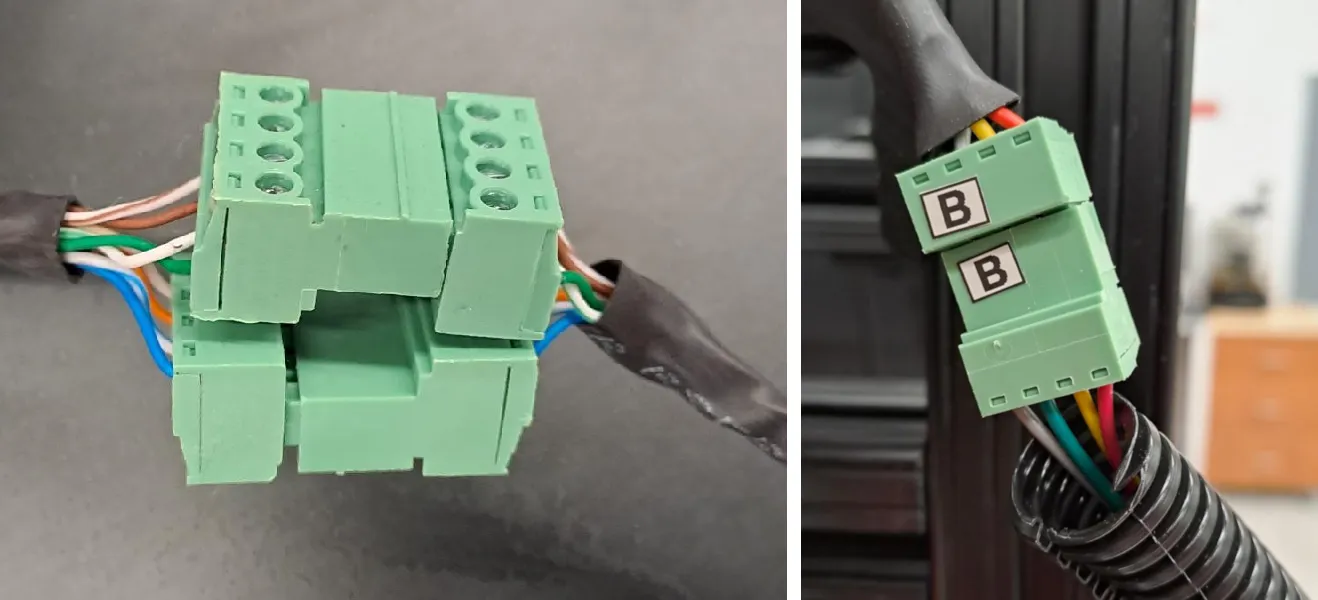
The Button Box, the Temperature & Humidity and the LED tower need to be connected to their corresponding cables through their green end connectors, which are labeled to their respective Vignette cables. The LED tower cable goes behind the Screen, and the other two have their cables in front of them. (When in doubt, try to match the colors of the cables)
1.2 The Tablet
The tablet mount needs to be tightened into the table close to the power outlets, so the tablet can be plugged using its USB-C cable. It is not necessary to keep the tablet connected at all times, but doing so will ensure the tablet does not unexpectedly run out of battery.
1.3 Starting up
Once all parts have been set up, the Vignette is programmed in such a way that it will start up mostly by itself once plugged. If the TV does not turn on by itself, turn it on manually with the TV’s remote controller.
After the initial splash screen, a grey screen with a logo should pop up. Wait for a few seconds for Home Assistant to bring itself up on the screen. If you are instead faced with a "Unable to connect. Firefox can't establish a connection to the server at homeassistant.local:8123", it means that the Vignette was not shut down properly (see section bellow). After around 2 minutes pressing "Try Again" should connect to Home Assistant.
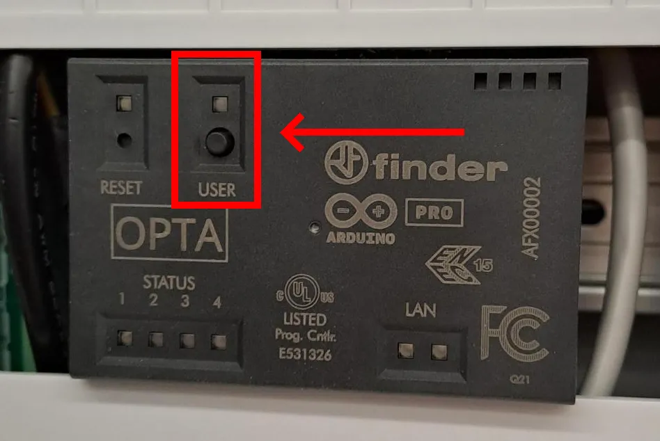
Once Home Assistant is fully running, The Arduino OPTA needs to be restarted so it can properly connect to Home Assistant, otherwise the Button Box and the LED tower will not work (In Home Assistant, these elements will show up grey instead of blue). To fix this, simply press the USER button once, which commands the Arduino to reset, indicated by the LAN LEDs in the Arduino turning off for a second.
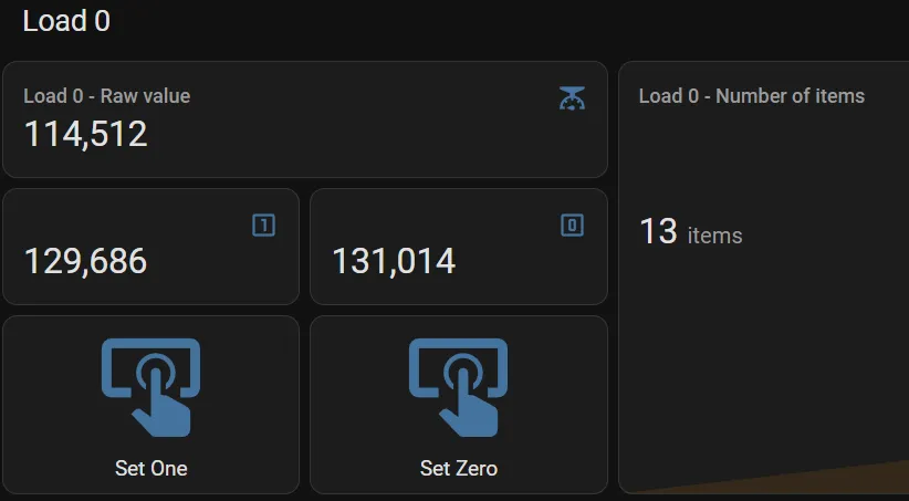
After some time, the load sensors might drift off on their sensed values. It is recommended to check the calibrations of the 3 bins and, if they have drifted too much, redo calibrations on them. This can be done through the LOAD SENSORS dashboard. For each load cell, you can see the actual value it is giving. The important thing to do here is to press the Set Zero and Set One buttons to record the weight of the empty tray and the tray with a single object respectively. The Vignette is supplied with extra Smart Plugs that can be used as examples for this, but the calibrated "object" can be anything available at hand.
1.4 Shutting Down
To properly shut down the Vignette, it is necessary to first shut down Home Assistant. This can be done by either pressing Ctrl + Alt + Del on the keyboard and confirming the shutdown, or by pressing the Windows key and clicking on the power button located on the upper-right corner. This is necessary as Home Assistant needs to properly save and close it's database. If not, it will take a few minutes to recover it from a forced shutdown (after which it will go back to working normally).
After fully shutting down Home Assistant, it is now safe unplug the Vignette.
Troubleshooting
Problem: Both the Button and the LED tower are not working.
Likely reason: The Arduino OPTA was not restarted after Home Assistant was fully set up.
Solution: Open the case containing the microcontrollers. On the Arduino OPTA, press the USER button once. This restarts the Arduino. The buttons and the LED tower should work after a few seconds. (If either is still not working, see the next problem)
Problem: The Button or the LED tower are still not working after restarting the Arduino.
Likely reason: Whichever is not working was likely not plugged back in while setting up the Vignette.
Solution: Find the end of the wire from the button box or the led tower (whichever is not working).
As shown in the images below, the connection for the Button box (Left image) comes in pairs and the cable should come from the back of the table. The connection for the LED Tower (Right image) should be close to the TV, behind it, and labeled B (there is another connection labeled A which belongs to the temperature sensor).
If the error persists, there may be a fault on the wiring (broken wire) or the components themselves (broken LED light) and deeper maintenance may be required.
Problem: The load cells/weight sensors are not measuring the trays correctly
Likely reason: The sensors are either not calibrated, or there is a fault on the connection.
Solution: First we need discard the possibility that the sensors are not working. In Home Assistant head to the LOAD SENSORS dashboard and scroll to the section of the sensor you wish to troubleshoot. We will be focusing specifically on the readings of the "Raw Value". You will need to push down the load cell you want to test and look at the reaction of the Raw Value.
- Option 1: If the Raw Value does not change and stays on a 4 digit value, or if it constantly jumps around independently of the load cell being pressed or not, then there may be a faulty connection.
- Option 2: If the Raw Value responds appropriately to force being applied to the load sensor (you can identify a change of the Raw Value proportional to the force applied), then the load cells are working correctly and they just need proper calibration to function as expected. For this, refer to the Vignette use instructions> Section 1.3 > Last paragraph.