
Agricultural Computer Vision Vignette Operation & Maintenance Manual
Created by The University of Georgia as a part of the Georgia Artificial Intelligence in Manufacturing Project
Build and Documentation by Marcus DiBattista
Table of Contents
- Overview
- Startup Procedure
- User Interface & Touch Points
- Recommended Usage
- Components & Wiring
- Main Python Script
- Model Training Instructions
- ESP-32 Microcontroller Programming
- Local Networking & Integration
- Transportation
- Troubleshooting & Maintenance
- Parts List
Overview
The Agricultural Computer Vision Vignette was developed with the purpose of creating a simple demonstration of a fully-implemented computer vision quality detection system with an agricultural use-case. This station is designed to be stand-alone, internet-independent, and highly mobile with sturdy wheels and frame. The demonstration is to show that low-cost, fully integrated computer vision solutions are possible with open source software and inexpensive hardware. The demo uses a YOLOv11 computer vision architecture running on a base M4 Mac Mini and an ESP-32 microcontroller for component and sensor interface. This station can be used for exposure to the capabilities and use-cases of computer vision AI techonlogy as well as for teaching how a fully integrated system works.
Startup Procedure
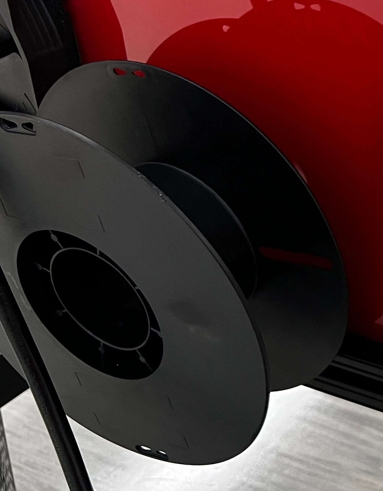
The startup procedure is simple, as it only requires access to standard wall power. Use the plug wrapped around the spool in the back and plug into any standard wall outlet. Once the vignette is plugged in, the vignette will automatically initiate the start up sequence, starting with a loading screen. After the loading screen the demo will be ready to use.
User Interface & Touch Points
The user interface has 6 main components, 5 of which are touch points for interaction and adjustments, and 1 is the display interface. The purpose of these are to allow the user to make adjustments or to test the machine, as well as to provide feedback on performance.
Display
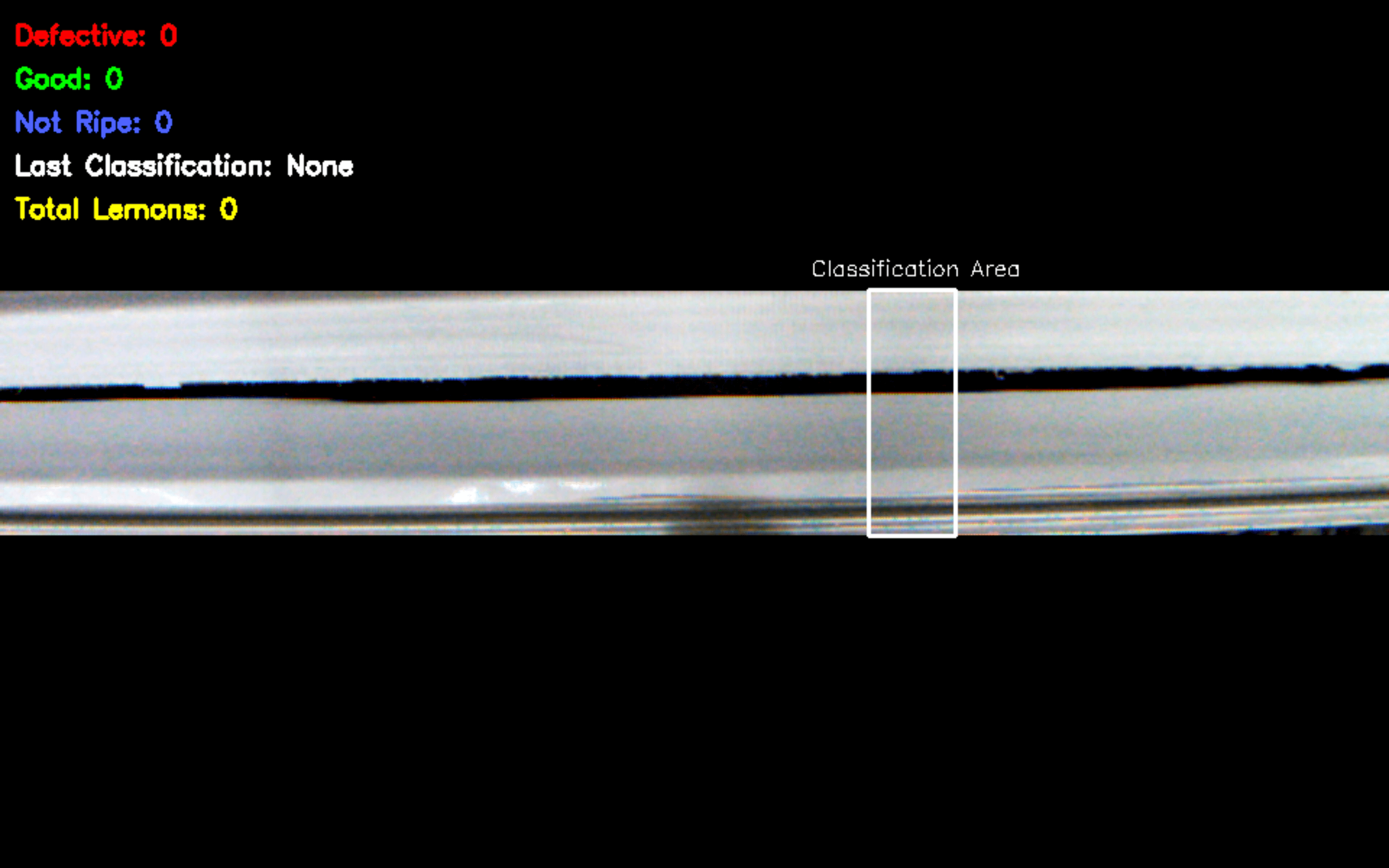
The Display shown below is the main point of feedback to the user, displaying the camera feed, the area in which a classification is set, and the counts for each classification since the machine was last turned on. As a lemon passes by the camera's view, the display will create a bounding box around the lemon with it's classification. This allows the user to see the real-time prediction of the model as the lemon rolls down the ramp. The counts in the top left corner of the screen include number of defective, good, and unripe lemons, as well as the classification of the latest lemon to roll down the ramp and the total number of lemons.
Air Pressure Regulator & Gauges
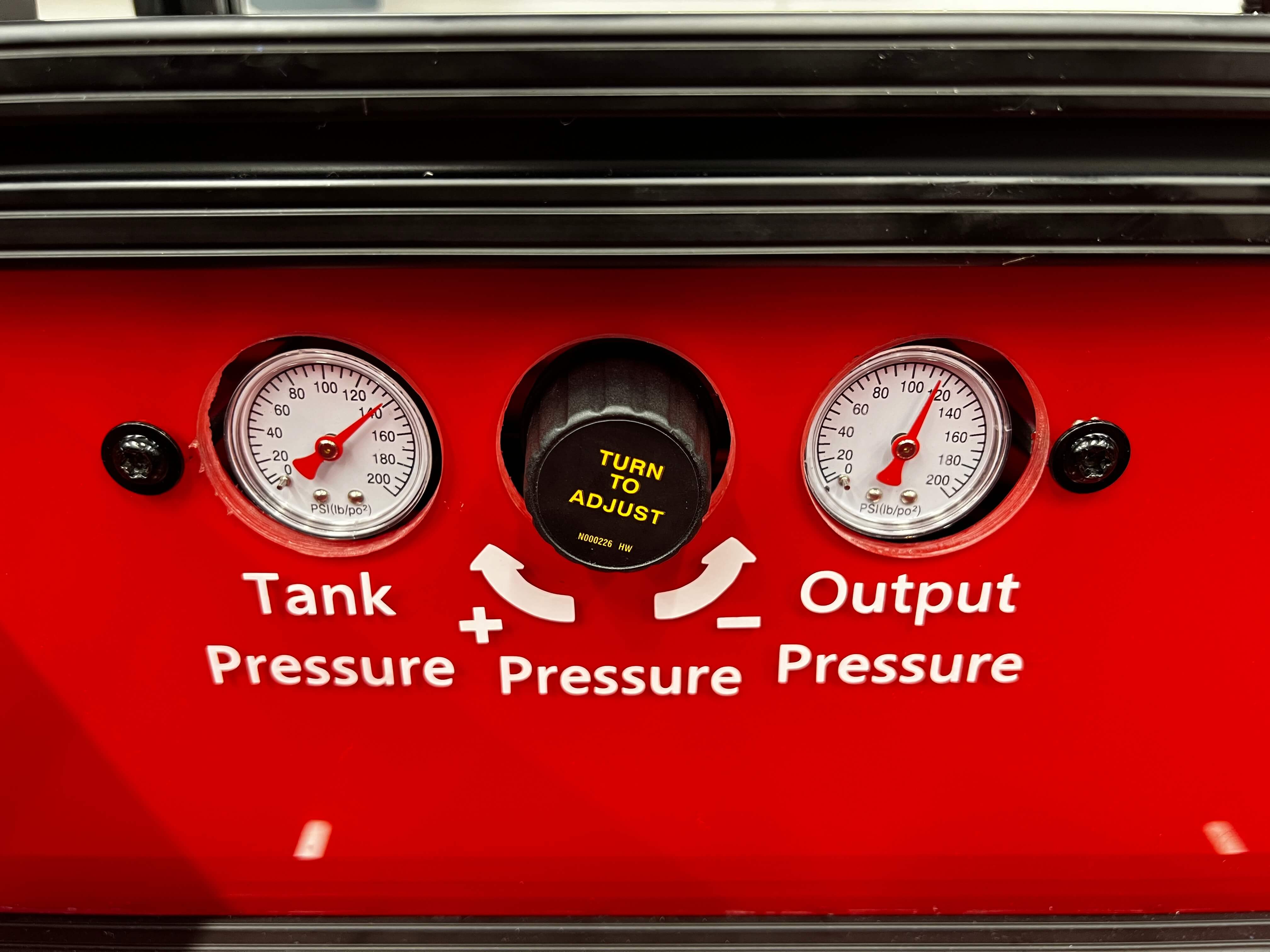
The air pressure regulator and gauges are included to give the user control over the ejection power for bad lemons. Increasing the pressure by turining the adjustment knob clockwise will increase the power of the lemon ejector, while decreasing the pressure by turning counter-clockwise will have the opposite effect. The gauge left of the pressure control knob displays the pressure available inside the main compressor tank, and the gauge right of the knob is the adjusted output pressure both in pounds per square inch (psi). Reccomended output pressure is 70 - 100 psi, it is not recommended to operate the machine above 115 psi.
Lemon Buckets
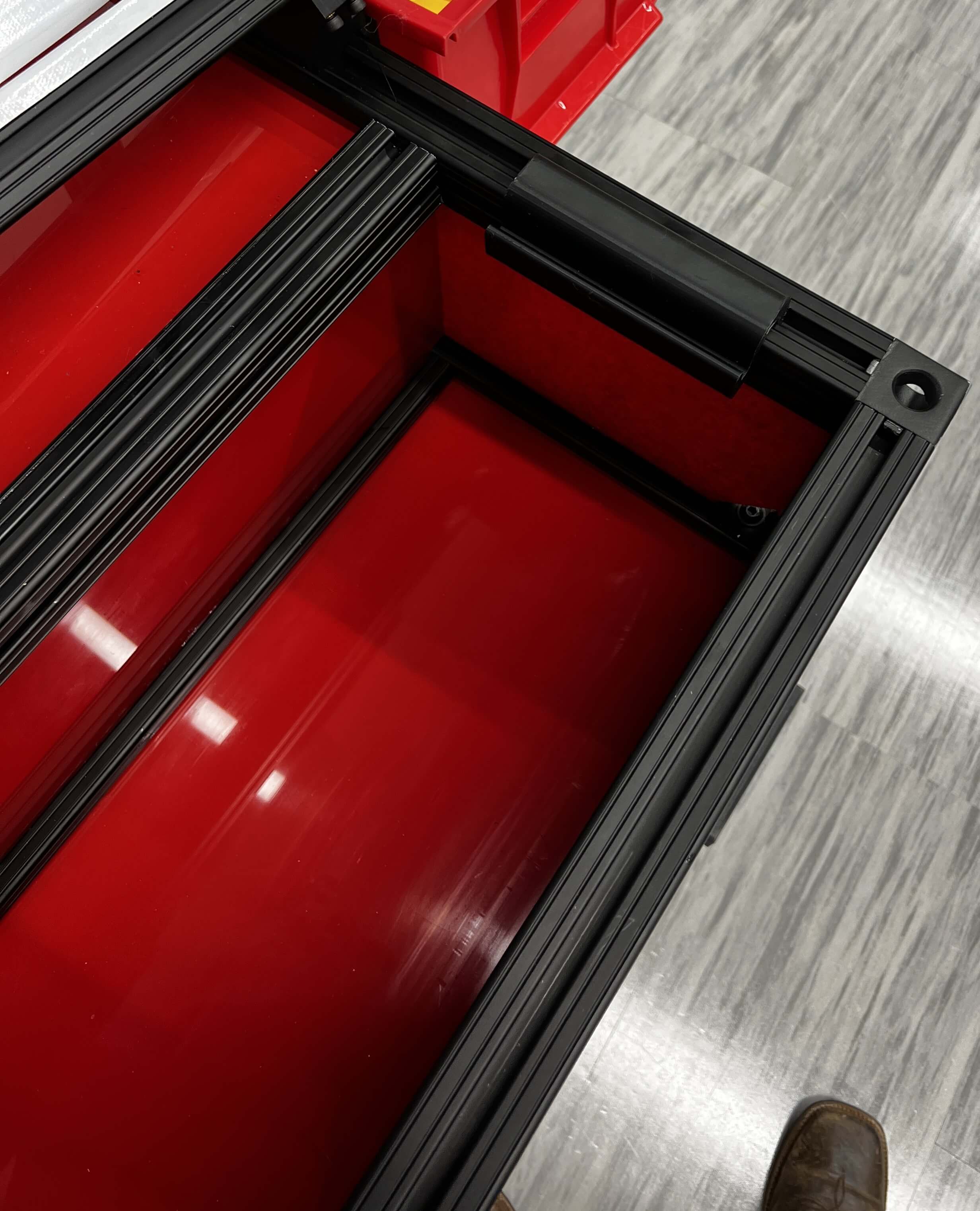
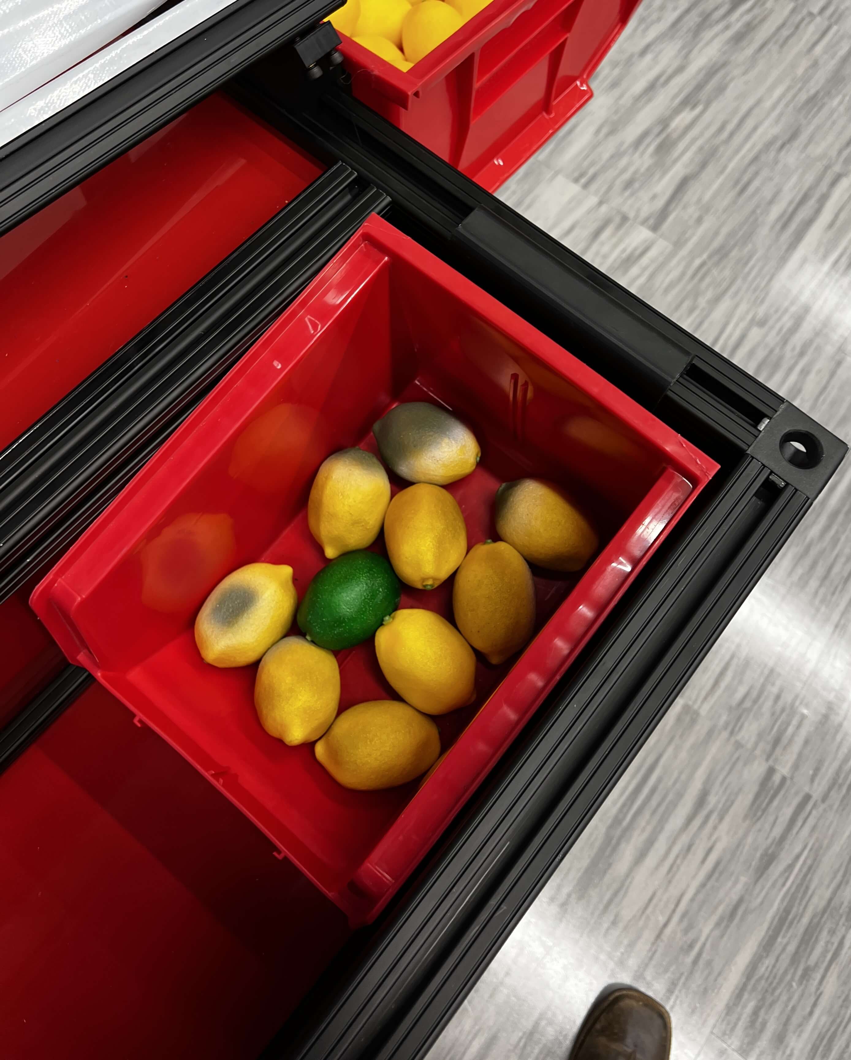
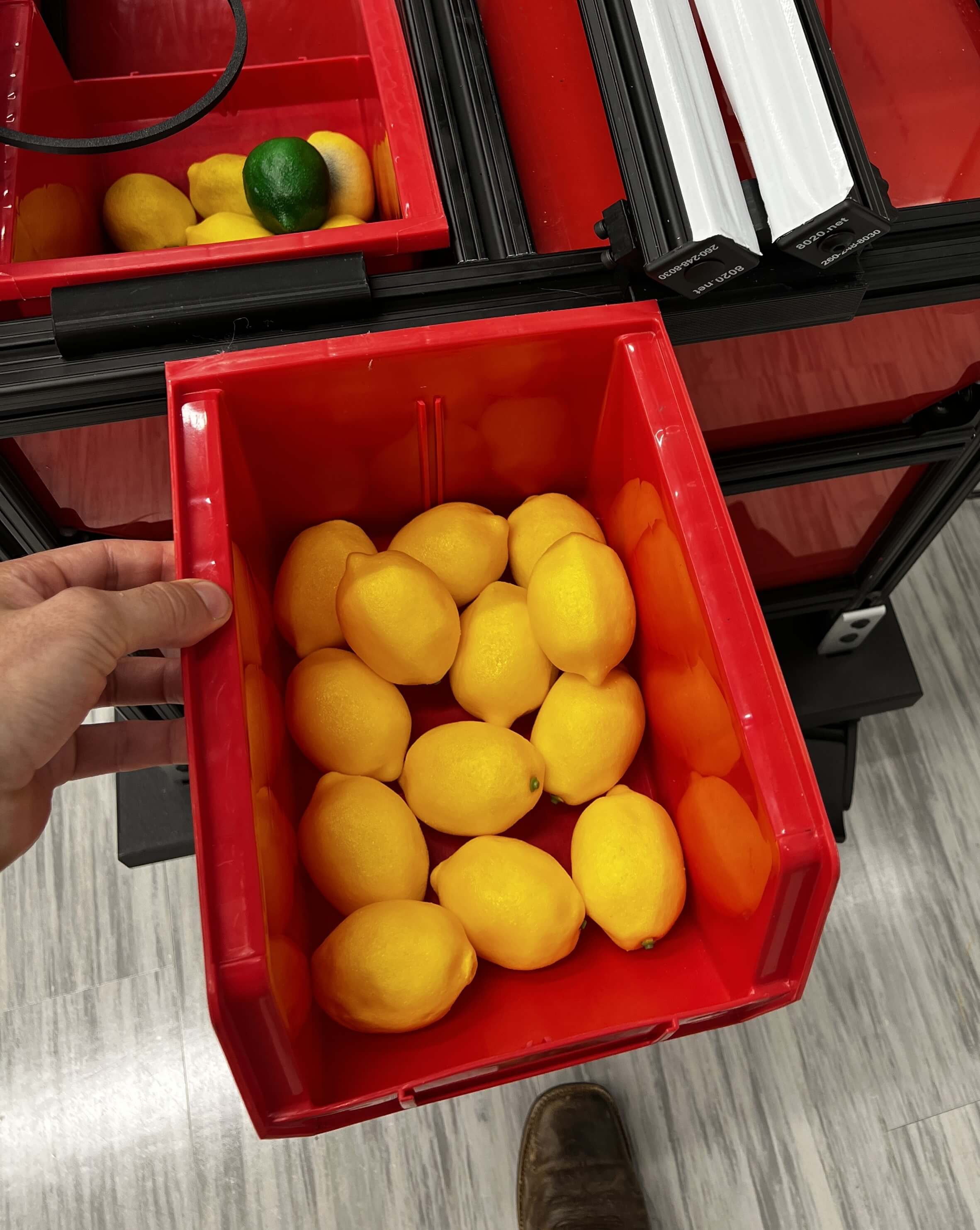
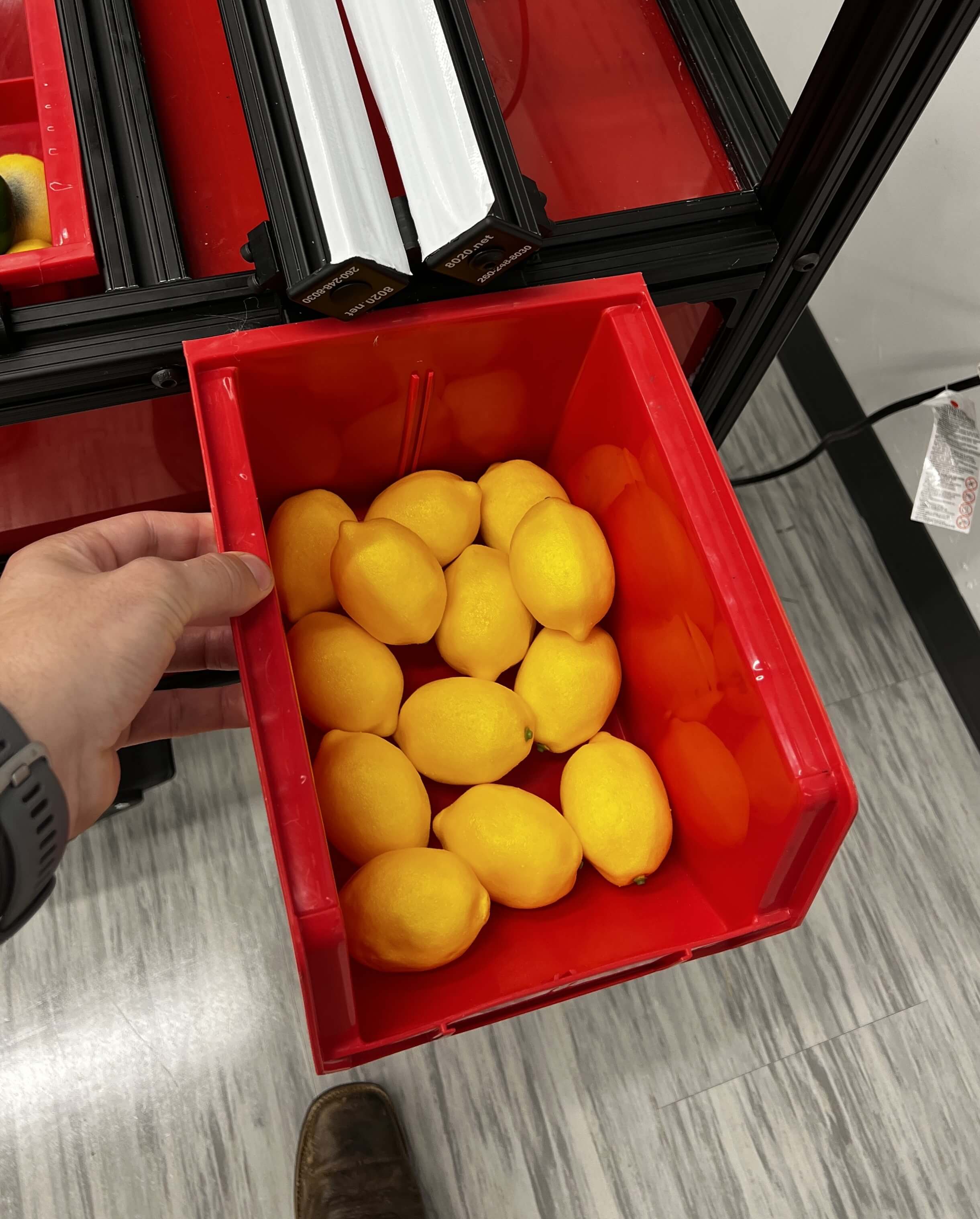
On the vignette there are 2 buckets, one intended for defective (rotten or unripe) lemons and one for acceptable lemons. When the system is operating, the lemons will automatically be sorted into the correct buckets when led down the ramp. These lemons can then be picked from the buckets and placed at the top of the ramp to test again. If needed these buckets can be removed. The bad bucket can simply be picked up out of place, and the good bucket can be slid horizontally out of place. The good bucket's mount is integrated into the right ramp mount, however the bad lemon bucket's mount is a separate file and is provided as agcv_bad_bucket_mount.3mf. The buckets also can have an optional part secured to the back of the buckets with double sided tape to make them mount more upright, and that file is provided as agcv_bucket_offset.3mf.
Proximity Sensor
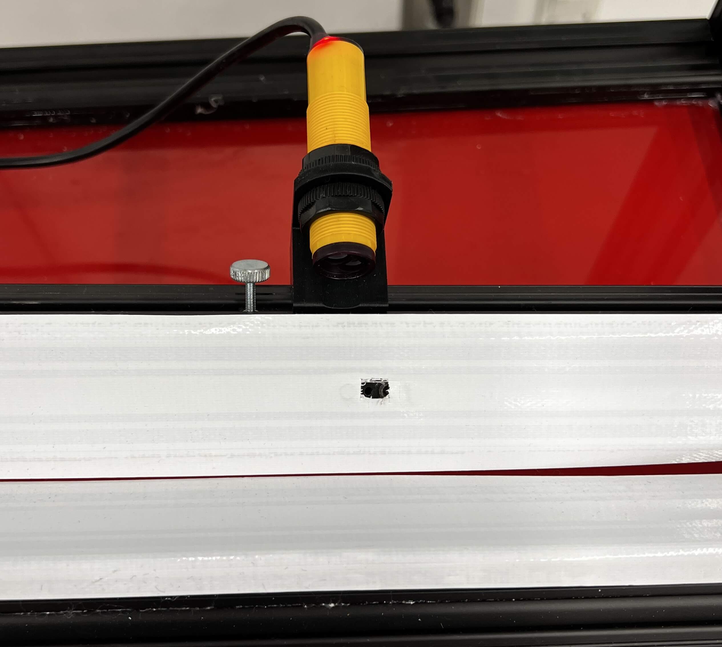
The yellow proximity sensor is used to detect the moment the lemon reaches the air nozzle. This is to make ejection timing more precise. The proximity sensor uses an infrared reflection to detect when an object is within the desired distance from the sensor. This distance can be tuned with the bronze flathead screw on the back of the sensor. Modification of this distance is not recommended but it is available for more advanced users. The sensor can also be moved left and right along the rail by unscrewing the silver tension screw left of the sensor and sliding the mount. This adjustment will change the timing of the air ejection. The red LED light on the back of the sensor will light up when the sensor is not detecting an object, and it will shut off when an object is detected.
Computer Vision Camera
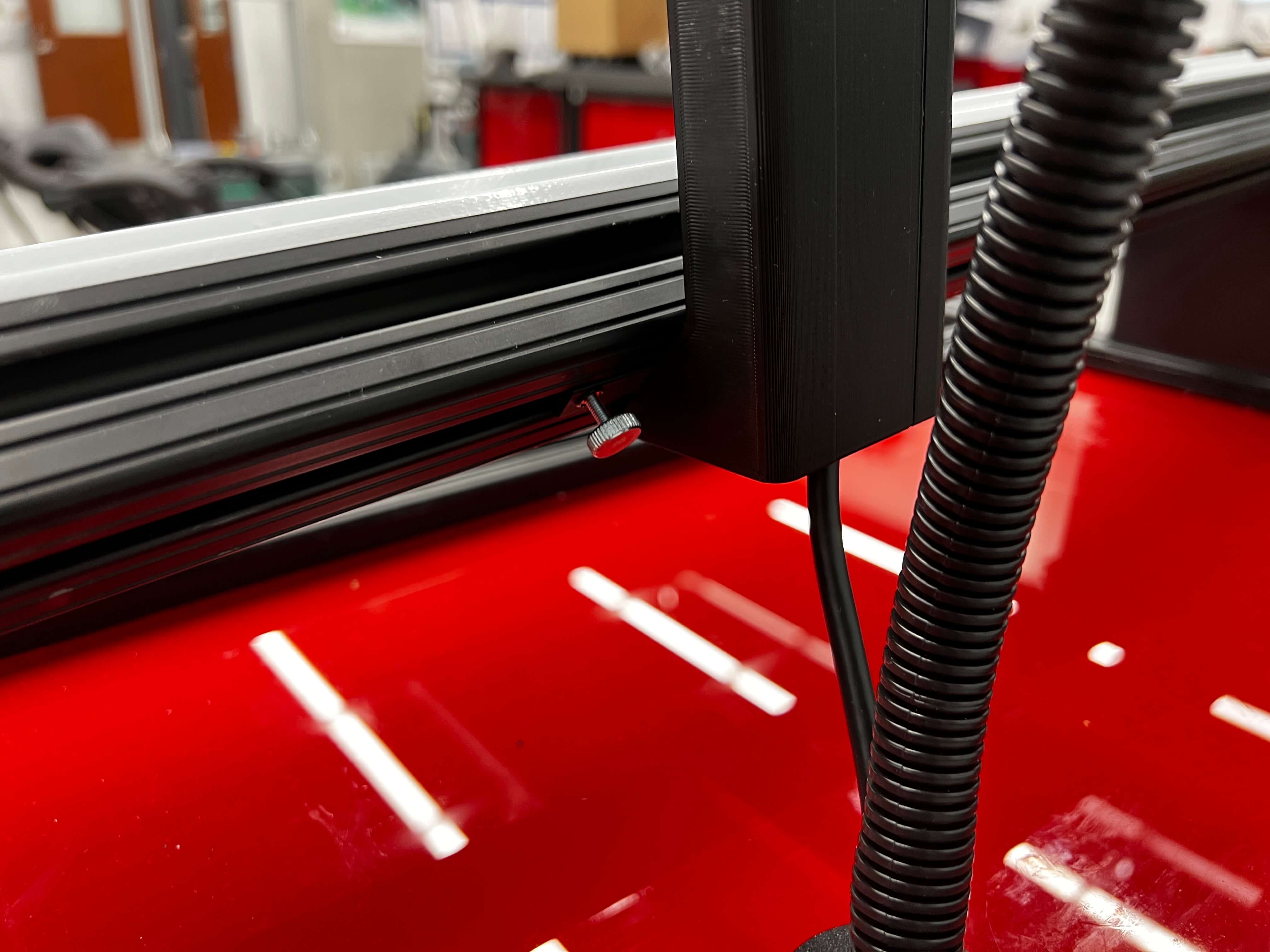
The camera for the computer vision system is mounted to the underside of the ramp with a tension screw holding it in place also located on the underside. If there is a desire to move the camera along the ramp, the tension screw can be loosened and tightened again when the camera is in the desired position.
Backboard & Basketball Hoop
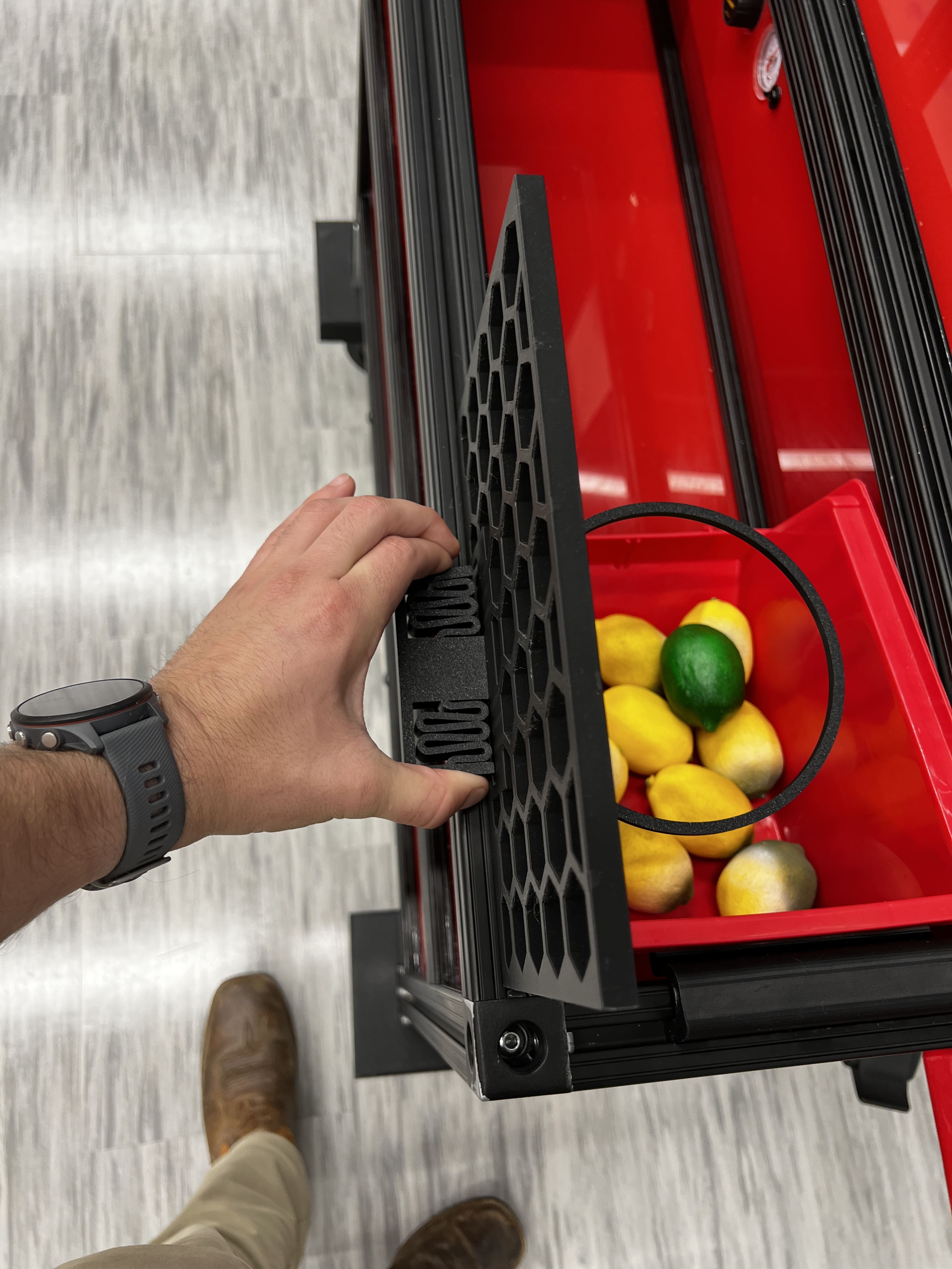
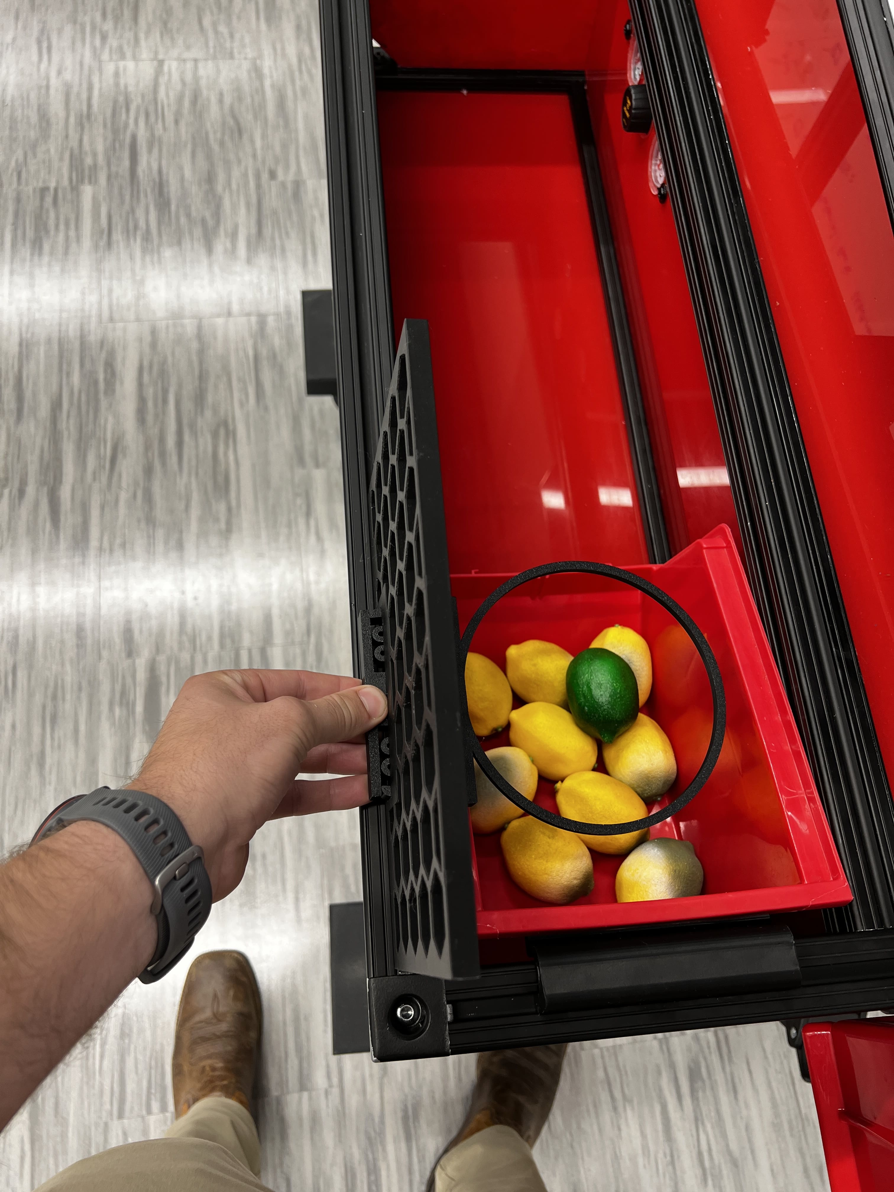
The backboard & basketball hoop are located in front of the bad lemon bin and are there to block lemons from over-shooting and to provide a more engaging and fun experience for the user. The backboard is free to move along the rail without constraint. The hoop is removable by squeezing the springs clasps on the back of the hoop and pushing the hoop forward. This is highly reccomended if the station is to be transported, especially if it is not standing up during transportation. The hoop removal process is shown in the images below. These components are both 3D printed and the 3D models are provided as agcv_backboard.3mf and agcv_hoop.3mf.
Recommended Usage
This demonstration is designed to be able to classify and sort the provided prop lemons into 3 classifications and 2 bins. The recommendation for using this station is as an exposure and preliminary learning tool to demonstrate a potential use case of a fully integrated computer vision system. This station can also be used to show some of the tuning parameters needed in order to fully integrate a system such as sensor positioning, ejector power / pressure, and lighting. Each of these factors has the ability to affect how well the computer vision or ejector system works. While the system is programmed to preform at a high level out of the box, certian conditions can cause the system to mis-classify or fail to eject such as running lemons down the ramp too close to one another, at too high of a speed, or without proper lighting. That being said, the system is capable of running multiple lemons down the ramp at the same time as long as these factors are considered.
Components & Wiring
Wiring Diagram
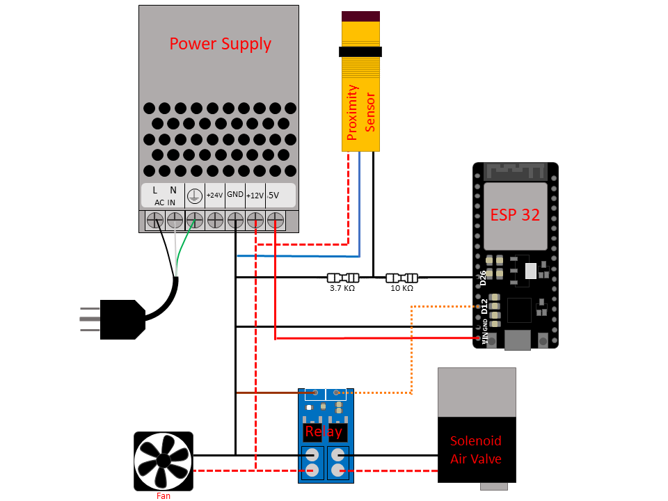
In the wiring diagram below, the red dashed line is all wires leading to the +12 volt terminal on the power supply. The solid red lines go to the +5 volt terminal.
Mac Mini
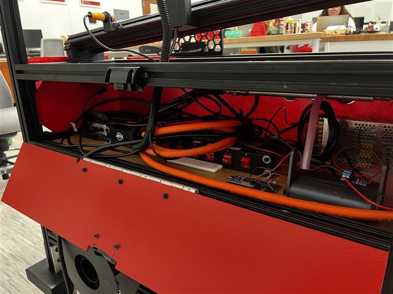
The Mac Mini computer serves multiple purposes in the system, mainly to run the computer vision model, send messages when lemons are detected, host the MQTT broker, and display the live detection display. All of these functions run automatically when power is connected using an autostart script that activates the correct python environment and runs the main python script on startup. More details on the details about the python script and model training instructions can be found in their respective sections. The Mac Mini is connected to main power to the switch board, the TV via HDMI, the camera via a USB type A to 90 degree USB type C cable, the Wi-Fi router via LAN cable, and there is an additional USB type C to USB type A adapter available for a keyboard and mouse if desired. The computer is hard mounted to the vignette using the 3D printed mount provided as agcv_mac_mini_mount.3mf and can be accessed through the back of the station. The exact Mac Mini used is the base spec M4 Mac Mini. This component can be switched off from switch 5 on the power switchboard with the label "MAC".
ESP-32
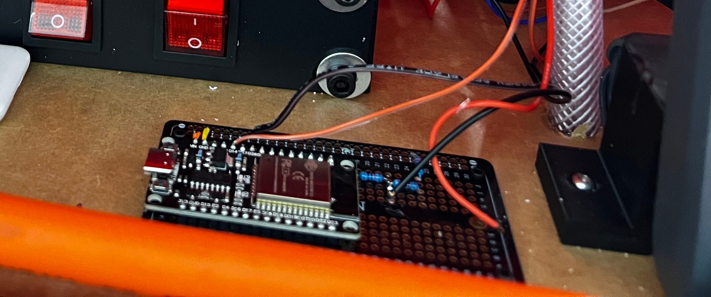
The ESP-32 is a microcontroller that uses programmed logic to decide when to activate the solid state relay and the electric solenoid air valve, to effectively eject defective lemons. More on the programming of the ESP-32 can be found in the ESP-32 Microcontroller Programming section. The ESP-32 is connected to the power supply with 5 volts and ground on the respective VIN and GND pins. The board is connected to the proximity sensor through the D26 pin with a voltage divider so that the correct voltage is supplied to the signal pin. The board is also connected to the solid state relay via the D12 signal pin. These connections along with the Wi-Fi connection to the local network allows the ESP-32 board to use MQTT messages from the computer vision system along with signals from the proximity sensor to effectively make decisions on when to activate the relay and eject lemons. If desired, the ESP-32 can be reprogrammed via the USB type C port on the board using Arduino IDE. While this can potentially cause the station to lose function if improperly reprogrammed, the board can always be reflashed with the original program to return function.
DC Power Supply
The DC power supply is required to convert 120v AC wall voltage into 12 volt DC and 5 volt DC terminals for the different electronic components to use. There is also a 24 volt DC terminal, however it is not used in this system. This power supply uses clamping screw terminals that clamp down on wires to make a connection. The proximity sensor, fan, and electric solenoid air valve all require 12 volt power, while the ESP-32 requires 5 volt power. The component used in this system can be found on amazon here. This component can be switched off from switch 7 on the power switchboard with the label "PWR SUPPLY". Doing so will cut power to all devices powered by the power supply including the ESP-32, proximity sensor, intake fan, relay, and electric solenoid air valve.
Wi-Fi Router
The Wi-Fi Router creates a local network for the Mac Mini computer and ESP-32 microcontroller to communicate on. The Wi-Fi router is connected to power through the power switchboard and to the Mac Mini through a LAN cable. If power is cut to the router using switch 6 labeled "ROUTER", it takes around 40 seconds for proper function to return. The link to the router on amazon is here. The 3D printed mount used to keep the router in place is agcv_router_mount.3mf.
Solid State Relay
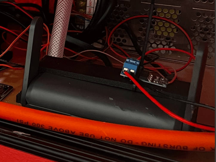
The objective of the relay is to control when power is provided to the Electric Solenoid Air Valve. The solid-state relay operates off the signal wire on pin D12 from the ESP-32 and ground. The relay is also connected to 12 volt power and ground on the VIN side of the terminal block and is connected to the positive and negative terminals of the Electric Solenoid Air Valve on the OUT side of the terminal block. The relay is mounted on top of the Wi-Fi Router. If desired, a standard relay can also be used, however the wiring would change slightly to accomidate separate power to the relay.
Electric Solenoid Air Valve
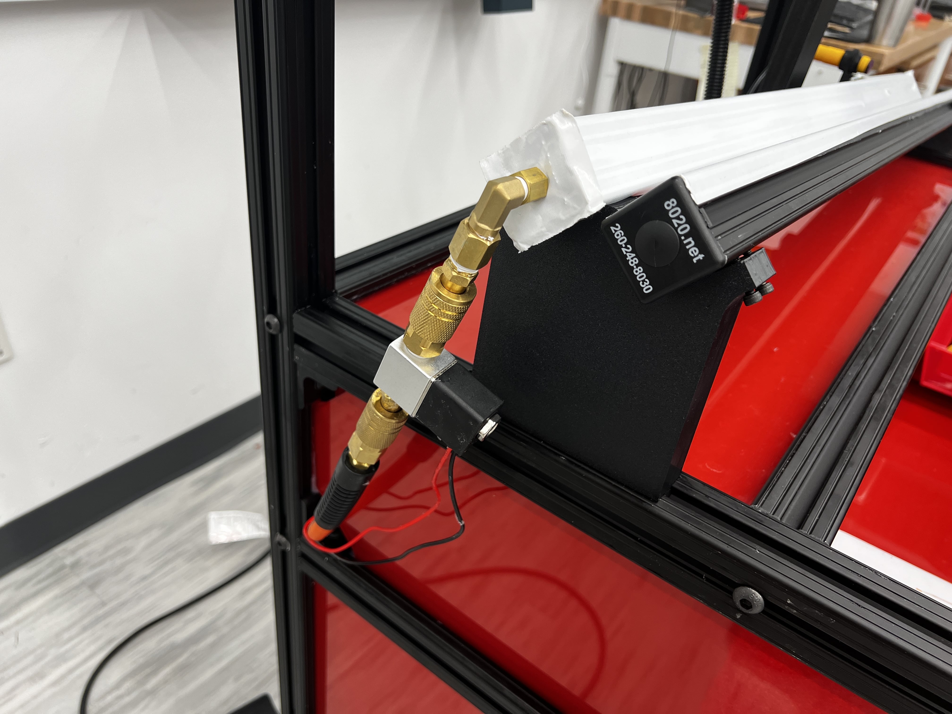
The electric solenoid air valve's purpose is to control when air is flowing through the lemon ejection nozzle. The solenoid works on 12 volts DC and is normally closed. The part is located on the left side of the station connected to the orange hose and the brass fittings leading into the ramp. The thread size is 1/4" NPT, however the thread size is further reduced to 1/16" NPT to fit the inside of the aluminium extrusion ramp. This component is connected to the solid-state relay that opens the valve when 12v power is provided. The link to the exact component on amazon is here. The valve's maximum operating pressure is 115 psi.
Proximity Sensor
The yellow proximity sensor is used to detect the moment the lemon reaches the air nozzle to make ejection timing more precise. The proximity sensor uses an infrared reflection to detect when an object is within the desired distance from the sensor. This distance can be tuned with the bronze flathead screw on the back of the sensor. Modification of this distance is not recommended but it is available for more advanced users. The sensor can also be moved left and right along the rail by unscrewing the silver tension screw left of the sensor and sliding the 3D printed mount which is provided as agcv_proximity_sensor_mount.3mf. This adjustment will change the timing of the air ejection. The red LED light on the back of the sensor will light up when the sensor is not detecting an object, and it will shut off when an object is detected. The sensor has 3 wires coming from it, a brown wire, a blue wire, and a black wire. The brown wire goes to the positive 12 volt power source and it is a dotted red line on the wiring diagram. The blue wire is shown as blue on the wiring diagram and is the negative or ground wire which is connected to ground on the power supply. The last wire is black on both the diagram and sensor and it is the signal wire. This wire has a voltage divider between the D26 pin on the ESP-32 and ground. The path to ground has a 3.7 kOhm resistor and the path to the D26 pin has a 10 kOhm resistor. The reason for the voltage divider is to reduce the voltage going to the ESP-32, since by default the sensor outputs 12 volts to the signal wire but the ESP-32 can only handle 3.3 volts on signal pins.
Power Switchboard
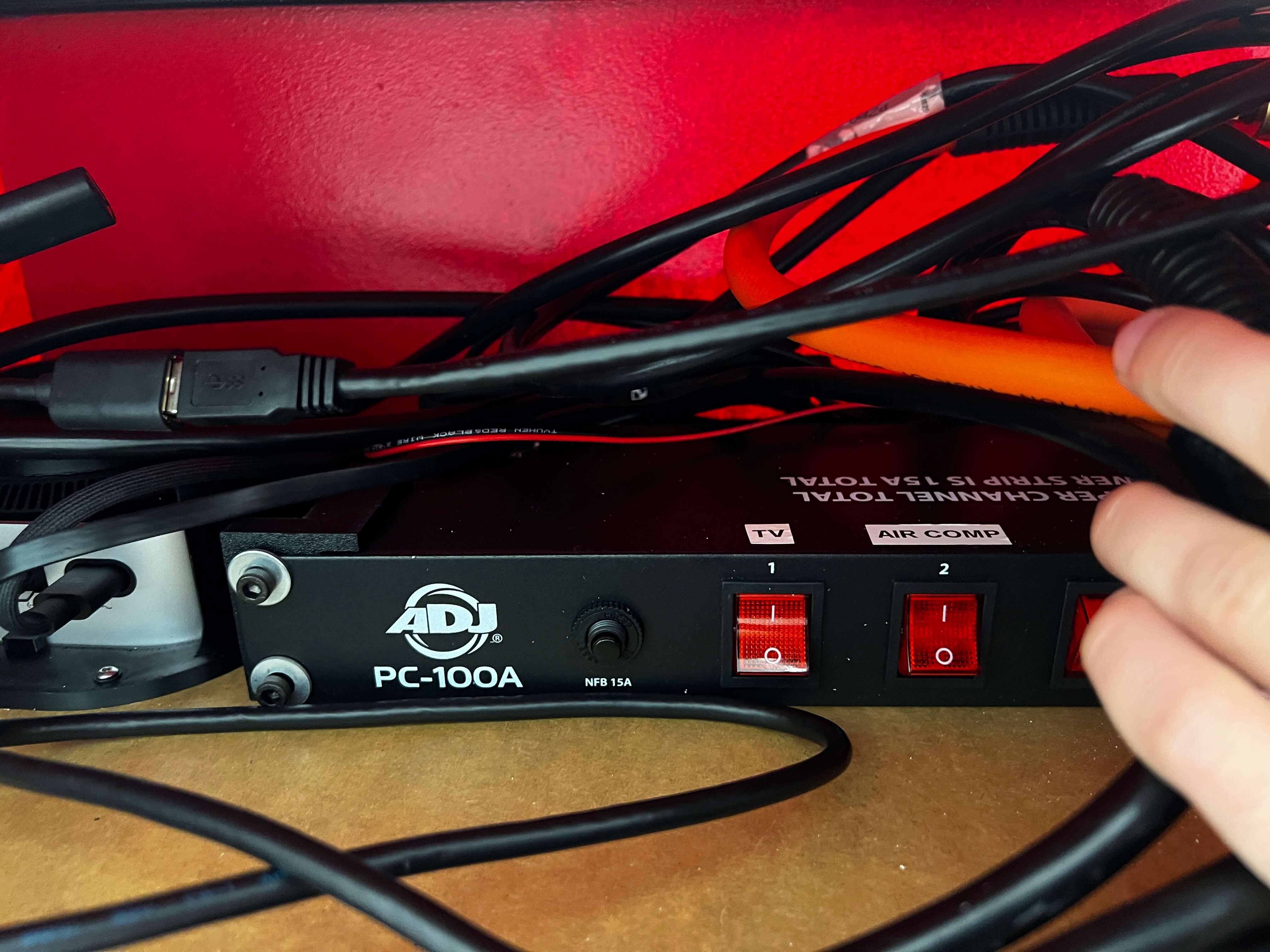
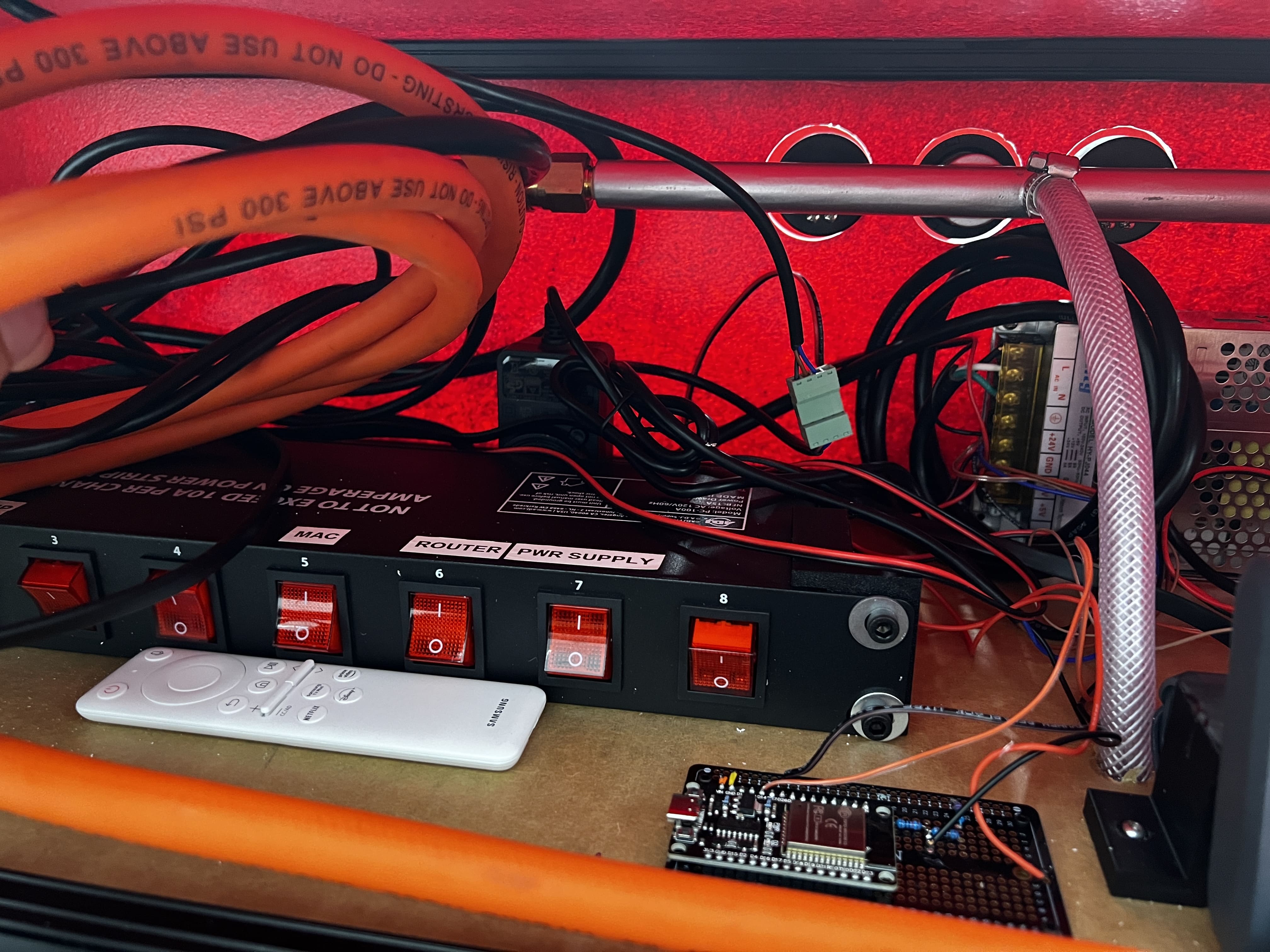
The power switchboard allows for individual components in the system to easily be switched on and off. It is located inside the hatch from the back of the station. The switchboard is mounted with a custom 3D printed mount and are provided as agcv_switchboard_mount_left.3mf and agcv_switchboard_mount_right.3mf. The switches are mapped to the following components:
- TV
- Air Compressor
- Empty
- Empty
- Mac Mini Computer
- Wi-Fi Router
- DC Power Supply
- Empty
Extruded Aluminium Ramp
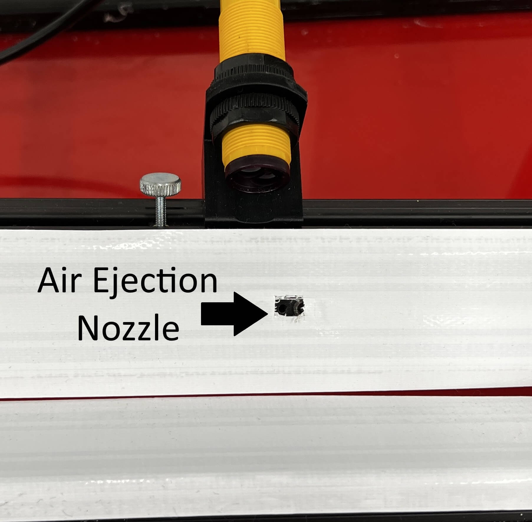
The ramp that the lemons roll down is constructed out of 2 1.5" hollow aluminum extrusion pieces and is mounted to the station with custom 3D printed mounts included as agcv_ramp_mount_left.3mf and agcv_ramp_mount_right.3mf. These mounts have tension screws that hold everything in place. White duct tape is layered on the contact surface to increase friction between the lemons and the ramp and to provide a uniform and bright background for the camera. The rear extrusion ramp has threads tapped on both sides; the side with the air line tapped with 1/16" NPT, and the other side closer to the nozzle is tapped with 3/8" - 16 UNC for a screw to prevent air leakage. All threads are wrapped in teflon tape to ensure a proper seal. The nozzle is located about 3/4 of the way down the ramp and was created by drilling a hole in the sealed internal chamber of the aluminum extrusion and attaching a 3D printed T-Nut style nozzle over the hole to decrease the distance from the lemons and decrease the diameter of the hole.
Air Ejection Nozzle
The air ejection nozzle's purpose is to blast defective lemons with air, shooting them into the correct bucket. The nozzle is located near the end of the ramp, and should be in around the same spot as the Proximity Sensor. The nozzle was created by drilling a hole in the sealed internal chamber of the aluminum extrusion and attaching a 3D printed T-Nut style nozzle over the hole to decrease the distance from the lemons and decrease the diameter of the hole. The 3D model of the nozzle is provided as agcv_nozzle.3mf.
Air Compressor
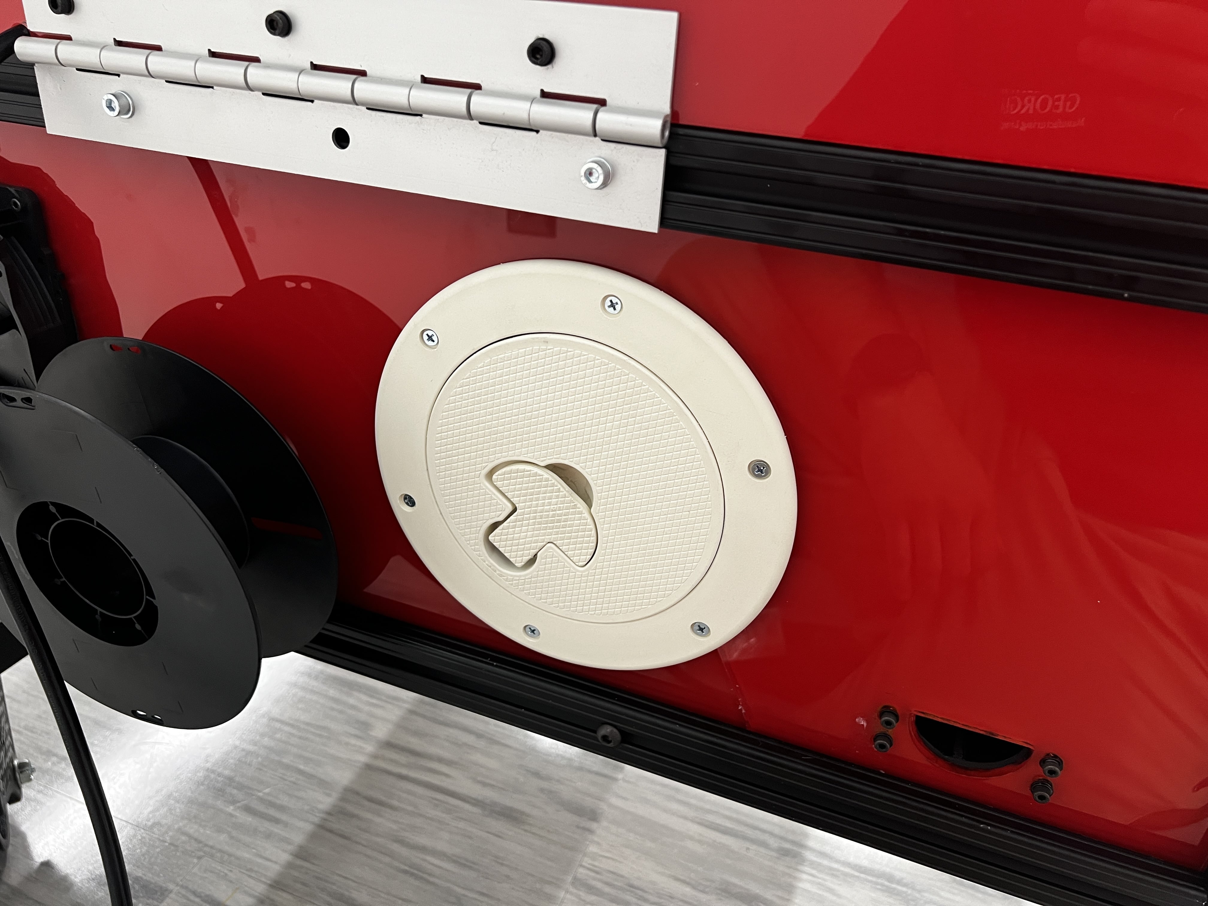
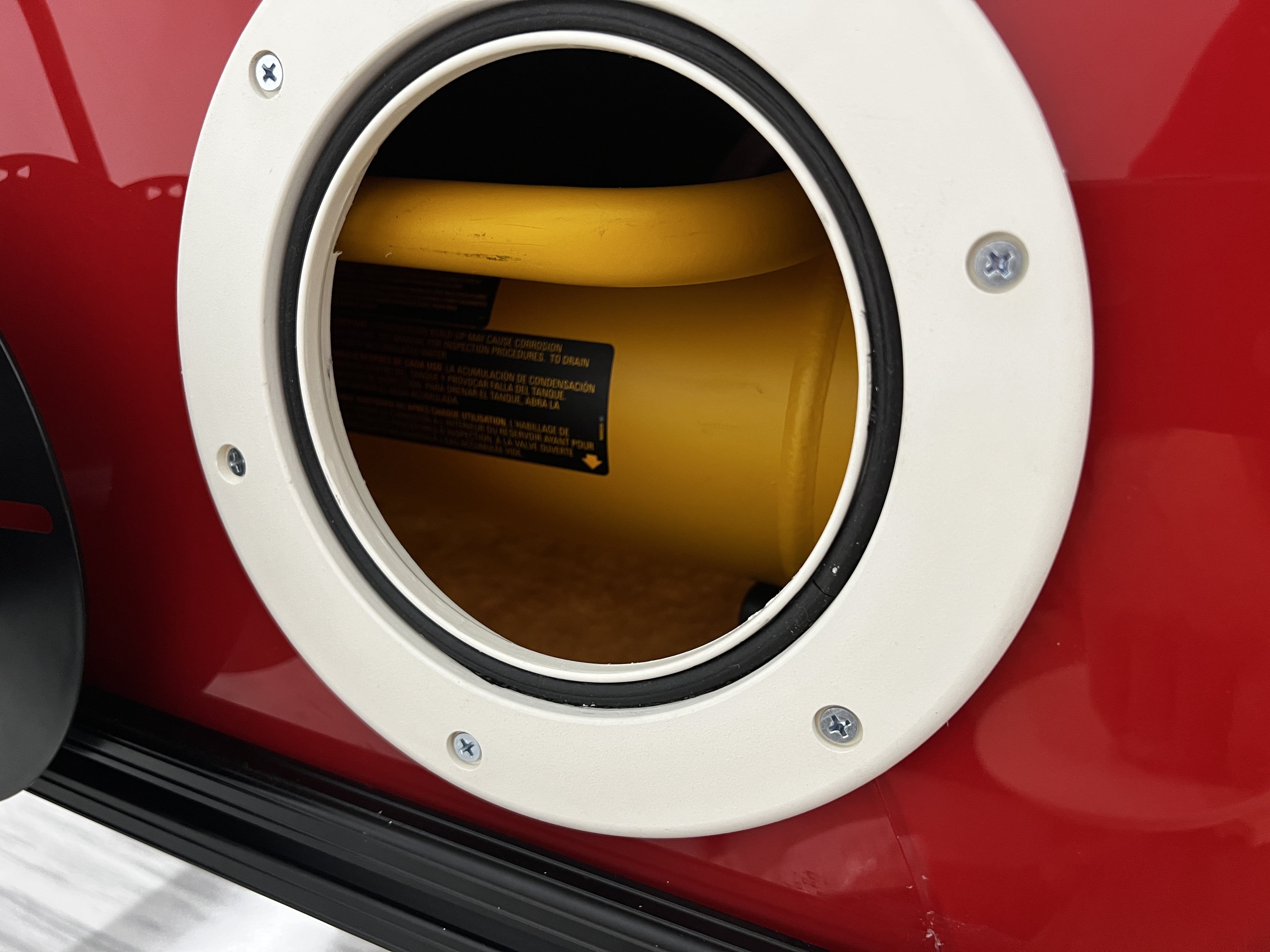
The air compressor is a a DeWalt 135 psi compressor with a 1 gallon air tank. The compressor was modified from it's original form, as the pressure regulator and gauges were moved to be accessible from the exterior. The compressor is plugged into the power switchboard and can be shut off from there if desired using switch 2 labeled "AIR COMP". The compressor is audible when running, and it will automatically run when pressure decreases below 100 psi. The compressor can be found on amazon here. The air compressor is hard mounted to the frame of the station and is contained in a sealed chamber, however if access is needed to the compressor, there is an access panel in the back of the station. If the vignette is left for an extended period of time without use, it is best practice to relieve the pressure inside the tank using the pressure relief valve located on the bottom of the yellow air tank. The air can also be purged through the brass purge pin on the right side of the pressure gauge mount accessible from the back hatch of the station.
Air Pressure Regulator
The air pressure regulator is mounted to an acrylic panel in the front of the station and is visible and usable from the exterior. The air pressure regulator and gauges are included to give the user control over the ejection power for bad lemons. Increasing the pressure by turining the adjustment knob clockwise will increase the power of the lemon ejector, while decreasing the pressure by turning counter-clockwise will have the opposite effect. The gauge left of the pressure control knob displays the pressure available inside the main compressor tank, and the gauge right of the knob is the adjusted output pressure both in pounds per square inch (psi). Reccomended output pressure is 70 - 100 psi, it is not recommended to operate the machine above 115 psi output pressure. Accessible from inside the hatch from the back of the station, there is also a purge pin on the right side of the the mount for the regulator if there is a desire to empty the air tank.
Intake Fan
The purpose of the intake fan is to force air into the sealed chamber and help dampen noise coming from the air compressor. This is to help with cooling and to make sure air is constantly being supplied to the compressor chamber. The fan runs off 12 volts on the DC power supply. Do not touch the fan while spinning as it could cause injury. The mounting tube inside the chamber that mounts to the fan is included as agcv_intake_mount.3mf and agcv_intake_tube.3mf.
Exhaust Muffler
The exhaust muffler is a baffled chamber intended to dampen sound coming from inside the sealed air compressor chamber while maintaining proper airflow for cooling. The muffler is a 3D printed piece that looks like a half-circle on the back of the station and is included as agcv_exhaust_muffler.3mf.
TV
The main display is a 43" Samsung Smart Monitor and it is plugged into the power switchboard. This TV is hard mounted with a TV mount that can pivot but is restricted by zip ties for safety. If the TV must be removed, there are 2 phillips head screws that unscrew to let the tv hang loose. This component can be switched off from switch 1 on the power switchboard with the label "TV".
Camera
The camera used to capture the video of the lemons rolling is an Arducam global shutter camera that is capable of capturing video at 19201200@50fps, or 960600@80fps uncompressed through a USB Type-C cable with USB 3.0. The link to the exact model on amazon is here. The camera uses a 95 degree FOV lens, and is capable of capturing high framerate video with little to no motion blur due to the global shutter. This is an important design aspect to consider if the capture of moving objects is desired. The mount used to properly position and secure the camera is able to be moved with a tension screw on the bottom of the mount if needed. The mount is 3D printed and also has a cap that is secured to the top of the mount with screws to prevent the cable from damage. Both 3D models are provided as agcv_camera_mount.3mf and agcv_camera_cap.3mf.
Main Python Script
This Python script serves as the "brain" of the fruit-sorting system, using computer vision and machine learning to classify fruit in real-time. It processes a live video stream, detects and tracks objects, classifies them based on a pre-trained YOLOv8 model, and publishes the classification results to an MQTT broker for the ESP32 microcontroller to act upon.
How It Works
The program begins by creating a splash screen with a progress bar using tkinter to indicate that the system is loading. Once this is complete, it initializes the main components:
MQTT Connection: The script connects to the MQTT broker using the paho.mqtt.client library. It's configured to publish classification messages to the fruit/classification topic.
YOLO Model Loading: It loads a custom-trained YOLOv11 model from the specified file path (best.pt). This model is what identifies and classifies the fruit in the video stream.
Video Stream: The script captures a video stream from a connected camera, which is configured to be a live feed.
Tracking and Smoothing: The core of the program is a streaming loop that processes each frame from the camera. It uses YOLO's track() function to not only detect objects but also to assign them a unique ID and track their movement.
A custom get_smoothed_label() function is implemented to prevent "flickering" classifications. It maintains a history of classifications for each tracked object. An object is only classified as a "DefectiveLemon," "GoodLemon," or "NotRipeLemon" if a significant proportion of its recent history matches that classification. This makes the system more robust to brief classification errors.
Classification Area: The script defines a specific rectangular area in the video feed as the "Classification Area." When a tracked fruit enters this area, its ID and smoothed classification are sent as an MQTT message. This ensures the classification is published at the precise moment the ESP32 is ready to sort the fruit.
Display: It displays the video feed in a full-screen window, showing bounding boxes around the detected fruit and key information like the number of each fruit type and the last classification sent.
Dependencies
This script requires several Python libraries. You can install them using pip:
opencv-python: For video capture and processing.
ultralytics: The core library for the YOLOv11 model.
paho-mqtt: For MQTT communication.
Pillow (PIL): For image processing in the tkinter splash screen.
tkinter: The standard Python GUI library (usually pre-installed with Python).
You may need to also address a specific environment variable for ultralytics:
os.environ["KMP_DUPLICATE_LIB_OK"] = "True"
This line is included in the code to prevent an error that can occur with the OpenMP runtime on some systems, particularly when running in specific Python environments.
Configuration and Customization
You will need to modify a few variables in the script to match your setup:
MQTT_BROKER: Set this to the IP address of your MQTT broker.
camera_index: The 0 typically refers to the built-in webcam. If you're using an external USB camera, you may need to change this to 1 or a higher number.
model: Update the file path to where you have stored your trained YOLO model (.pt file). For example:
model = YOLO("C:/Users/YourName/Desktop/best.pt")
yaml_path: This should point to your tracker configuration file. The code currently uses botsort.yaml.
The smoothing parameters can also be adjusted:
HISTORY_LENGTH: The number of recent frames to consider for smoothing. A higher number makes the classification more stable but less reactive.
DEFECT_THRESHOLD and GOOD_THRESHOLD: These floating-point numbers control the proportion of history required to confirm a classification. Adjust these to fine-tune the classification stability.
Important Note
The code is configured to run in full-screen mode and exit only when the ESC key is pressed. The cv2.namedWindow and cv2.setWindowProperty lines control this behavior. If you want to run it in a standard window, you can comment out those lines.
ESP-32 Microcontroller Programming
This will provide an overview of the ESP32 programming designed for the automated fruit-sorting system.
The program connects to a local network, communicates with an MQTT broker, and uses a proximity sensor to trigger a solenoid for sorting fruit based on an external classification.
System Overview
The sketch operates in a loop, waiting for two key events to occur:
- An MQTT message from the computer vision model publishing a lemon's ID and classification to the MQTT topic fruit/classification
- A physical trigger: A proximity sensor detects the fruit as it passes a specific point on a conveyor or sorting line
When the proximity sensor detects a fruit, the ESP32 processes the next item in a queue that has been populated by the MQTT messages. If the fruit's classification is "DefectiveLemon" or "NotRipeLemon", it activates a solenoid to divert the fruit.
How It Works
Setup and ConnectionsThe setup() function handles the initial configuration. It sets up serial communication for debugging and configures the I/O pins for the proximity sensor (INPUT) and the solenoid (OUTPUT).
It then attempts to connect to a local Wi-Fi network using the specified SSID and password. After a successful Wi-Fi connection, the ESP32 connects to the MQTT broker located at the mqtt_server IP address. Finally, it subscribes to the fruit/classification topic, which is the channel for receiving fruit classifications.
The Main Loop
The loop() function is the heart of the program. It constantly performs the following actions:
- MQTT Client: It calls client.loop() to maintain the connection to the MQTT broker and process any incoming messages
- Queue Timeout: It checks for a timeout. If the time since the last MQTT message exceeds timeoutInterval (1.2 seconds), it assumes something is wrong with the classification system and clears the fruitQueue to prevent mis-sorting
- Proximity Sensor Detection: It reads the state of the proximity sensor. The code uses a "rising edge" detection logic, which means it only takes action when the sensor state changes from LOW to HIGH. This ensures that a single piece of fruit triggers the action only once, preventing multiple sorting attempts for the same item
- Processing the Queue: When a rising edge is detected, the program takes the first item from the fruitQueue
- If the classification is "DefectiveLemon" or "NotRipeLemon", it activates the solenoid by setting solenoidPin to HIGH
- A small delay of triggerDelay (175 ms) is used to keep the solenoid open long enough to sort the fruit. This can be adjusted for machine tuning.
- The solenoid is then deactivated by setting the pin to LOW
- If the classification is anything else, the fruit is assumed to be good, and the solenoid is not activated
The callback() Function
This function is automatically called whenever a new message is received on the fruit/classification MQTT topic. It parses the incoming string, extracts the fruit's ID and classification, and adds this information as a new Fruit object to the fruitQueue. This queue acts as a buffer, holding the fruit classifications in the order they were received, ready to be processed when the proximity sensor is triggered.
Configuration
To use this sketch on your own hardware, you need to update the following variables with your specific network and hardware details:
- ssid: Your Wi-Fi network name
- password: Your Wi-Fi network password
- mqtt_server: The IP address of your MQTT broker
- proximitySensorPin: The GPIO pin the proximity sensor is connected to
- solenoidPin: The GPIO pin the solenoid relay is connected to
- triggerDelay: The duration in milliseconds that the solenoid will be active
Dependencies
This sketch requires the following libraries, which can be installed via the Arduino IDE Library Manager:
- WiFi: Included with the ESP32 board package
- PubSubClient: A popular library for MQTT client functionality
Local Networking & Integration
The networking of the vignette is done through a portable Wi-Fi router that allows the ESP-32 and Mac Mini to communicate. The devices communicate through a protocol known as MQTT, which requires a broker server to be running on the local network in order to function properly. The MQTT broker software is called Mosquitto Broker and it is running locally on the Mac Mini. Due to everything running locally on its own network, the system does not require internet access to function. The ESP-32 and Mac Mini are assigned static IP addresses in the router's configuration, therefore there is no issue with hard-coded IP addresses in the code of either script.
By default, the Wi-Fi sign in credentials are as follows:
- Wi-Fi SSID: AG_CV_GAAIM
- Wi-Fi Password: georgiaaim123
Transportation
The station is designed around transportability. For transportation throughout a facility, the large wheels allow simple and versatile transportation, and when the station needs to be stationary, each wheel has an easy-to-use foot brake that can be pushed down to stop wheel movement, and be pulled up to free the wheels. If the station is to be moved via truck to another location, the reccomended method is to ship standing up secured to a wall with any frame part with the front of the station facing the wall due to the fan and wire spool in the back. The hoop and good lemon bucket can both be removed and stored with the bad lemon bucket in the cubby for transportation. The station can also be transported on its front face laying down if necessary. Both buckets and the hoop must be removed for this, and it is recommended that moving blankets are used to prevent damage to the front of the station. Please take care to make sure the station is properly secured to a frame piece during transportation and that loose objects do not damage the TV or Camera Mount. DO NOT TRY TO TRANSPORT THE STATION IN ANY OTHER ORIENTATION EXCEPT FOR STANDING UP OR WITH THE FRONT FACE LAYING DOWN, AS THIS CAN CAUSE PERMANENT DAMAGE TO THE STATION. Due to the station's weight, it is reccomended that at least 2 people are present when trying to lift or lay down the station.
Bucket Removal
Both buckets are removable, with the bad lemon bucket being able to be easiy lifted out of place and the good lemon bucket being able to be slid out of place horizontally.
Hoop Removal
The hoop can be easily removed by squeezing the springs on the back of the backboard and pushing the hoop out.
Troubleshooting & Maintenance
Most issues with the machine can be solved by unplugging the machine and plugging it back in to restart the system. This guide can provide sources to other potential issues with the system. If any of the 3D printed parts break or go missing, all of the files to recreate them are included in this repository under "3d-models". The complete parts list is also provided with purchase links throughtout this documentation to referenced parts. The power switchboard is one troubleshooting tool that can be used to turn on and off specific components in the system if restarting the system does not fix an issue. Most issues with the machine can be solved by unplugging the machine and plugging it back in to restart the system. This guide can provide sources to other potential issues with the system. If any of the 3D printed parts break or go missing, all of the files to recreate them are included in this repository under "3d-models". The complete parts list is also provided with purchase links throughtout this documentation to referenced parts. The power switchboard is one troubleshooting tool that can be used to turn on and off specific components in the system if restarting the system does not fix an issue. If everything seems to be working normal on the display but lemons are not ejecting, first try restarting, then check to make sure the ESP-32 has a red LED light on, that the router is plugged in, and that there are no loose connections with the ESP-32 or solid-state relay.
Parts List
| Part Name | Description | Quantity | Purchase Link / File Name |
|---|---|---|---|
| ESP-32 | Microcontroller | 1 | Amazon |
| Arducam Camera | Global Shutter Camera | 1 | Amazon |
| Solid State Relay | High power dual mosfet switch | 1 | Amazon |
| Wi-Fi Router | Local network communication | 1 | Amazon |
| Mac Mini | Computer for CV and MQTT broker | 1 | Apple |
| TV (Samsung Smart Monitor) | Main display | 1 | Amazon |
| TV Mount | Main display mount | 1 | Amazon |
| Air Compressor | 135 psi, 1 gallon air tank | 1 | Amazon |
| DC Power Supply | Converts AC to 24V/12V/5V DC | 1 | Amazon |
| Electric Solenoid Air Valve | Controls air flow to ejection nozzle | 1 | Amazon |
| Intake Fan | Cools compressor chamber | 1 | - |
| USB C Right Angle cable | Connects computer to camera | 1 | Amazon |
| Proximity Sensor | Detects lemon position for ejection | 1 | Amazon |
| Lemon Buckets | Collect sorted lemons | 2 | ULINE |
| 1/4" Air Compressor Hose | Used to connect regulator to solenoid | 1 | Amazon |
| 1/4" NPT Brass Quick Connects | Fittings for connecting to Air Line | 1 | Amazon |
| 1/4" F to 1/8" M NPT Brass Fitting | Fitting to reduce air line diameter | 1 | Amazon |
| 1/8" NPT 90 Degree Brass Fitting | Creates 90 deg elbow for air line | 1 | Amazon |
| 1/8" F to 1/16" M NPT Brass Fitting | Fitting to thread into alum extrusion | 1 | Amazon |
| Threaded Heatset Inserts | Used to insert threads into plastic components | 1 | Amazon |
| M3 x 20mm Thumb Screws | Used as tension screws to hold components into place | 1 | Amazon |
| M10-1.5 x 35mm Hex Bolts (13pc) | Bolts for Wheels | 2 | Amazon |
| 1/2" SS Flat Washers (50pc) | Washers for Wheels | 1 | Amazon |
| M10-1.5mm Nylon Insert Locknuts (30pc) | Nuts for Wheels | 1 | Amazon |
| Solderable Breadboard | Breadboard for ESP32 & Resistors | 1 | Amazon |
| Resistor Kit (1350pc) | For resistors for Voltage Divider | 1 | Amazon |
| GE Advanced Silicone | Compressor Chamber Sealant | 1 | Amazon |
| Wheels | Large Wheels with Brake | 4 | McMaster Carr |
| Base Plate Mounting Foot | Mounting plate for Wheels | 4 | McMaster Carr |
| Latch | Latch for Rear access hatch | 1 | McMaster Carr |
| Gasketed Access Port | Access port for Air Compressor Chamber | 1 | McMaster Carr |
| Rail to Rail Hinge | Hinge for Rear Access Hatch | 1 | McMaster Carr |
| Complete Chassis Material | Complete order list for Frame chassis | 4 | McMaster Carr |
| 1.5" Black Hollow Extruded Aluminium | Lemon rolling surface & Frame | - | McMaster Carr |
| Exhaust Muffler | Dampens compressor noise | 1 | agcv_exhaust_muffler.3mf |
| Power Switchboard | Switches for all major components | 1 | agcv_switchboard_mount_left.3mf, agcv_switchboard_mount_right.3mf |
| Air Ejection Nozzle | Directs air blast to lemons | 1 | agcv_nozzle.3mf |
| Camera Mount | Mounts camera to ramp | 1 | agcv_camera_mount.3mf |
| Camera Cap | Secures camera cable | 1 | agcv_camera_cap.3mf |
| Router Mount | Holds Wi-Fi router in place | 1 | agcv_router_mount.3mf |
| Mac Mini Mount | Holds Mac Mini to frame | 1 | agcv_mac_mini_mount.3mf |
| Ramp Mount Left | Mounts left side of ramp | 1 | agcv_ramp_mount_left.3mf |
| Ramp Mount Right | Mounts right side of ramp & bucket | 1 | agcv_ramp_mount_right.3mf |
| Bad Bucket Mount | Holds bad lemon bucket | 1 | agcv_bad_bucket_mount.3mf |
| Bucket Offset | Optional, makes buckets more upright | 2 | agcv_bucket_offset.3mf |
| Proximity Sensor Mount | Mounts proximity sensor to rail | 1 | agcv_proximity_sensor_mount.3mf |
| Intake Mount | Mounts intake fan | 1 | agcv_intake_mount.3mf |
| Intake Tube | Directs air from intake fan | 1 | agcv_intake_tube.3mf |
| Backboard | Basketball backboard for fun/retention | 1 | agcv_backboard.3mf |
| Hoop | Basketball hoop for bad lemon bin | 1 | agcv_hoop.3mf |
| Wire Grommet | Wire Grommet for wires for external | 1 | agcv_wire_grommet.3mf |
Note: All 3D printed parts are included in the repository under "3d-models". For electronic components, refer to the purchase links provided. For any missing or broken 3D printed parts, print the corresponding .3mf file included in the repository under "3d-models". For non-3D printed components, refer to the purchase links provided. Please use caution to relieve any pressure before working on or replacing any parts within the pneumatic ejection system.